
Rendering with high quality silkscreen using EagleCAD and Fusion 360 integration.
I have developed very workable method for this which others may find useful. Please consider the following a tutorial until such time as the import to Fusion 360 works better. This assume you have already created a board layout in EagleCAD and have synchronized it with Fusion 360.
Please visit me at http://neltnerlabs.com if you need the highest quality fully customized equipment for scientific, industrial/chemical, consumer, or medical applications focused on startups.
1. In eagle, display the Dimension, tPlace, and tNames layers (unless you want to see others show up). Set your dimension lines to 0 width.
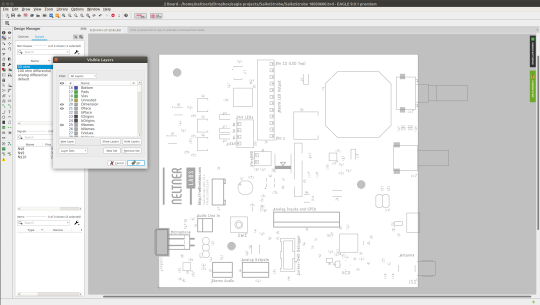
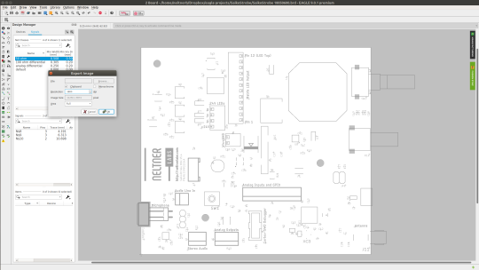
2. Export as an extremely high resolution image. I tried to do a dxf export to get vector graphics, but Inkscape couldn’t open the file. Weirdly, gerbview also chokes on the gerber files exported by Eagle CAM which is more worrying for other reasons, but a problem for another day. Even tried both X2 and regular Gerber… anyway, just export as a bitmap since that actually works. I export to clipboard as it requires further editing.
3. Copy into The Gimp.
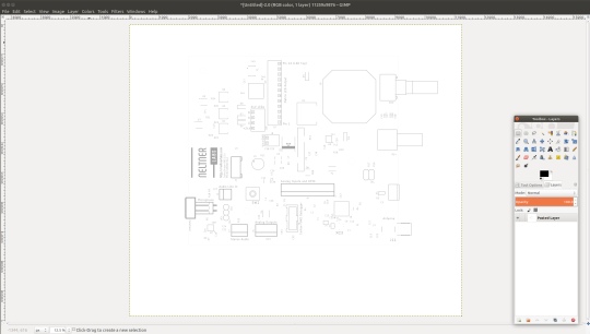
4. Crop the image just to the inside of the dimension lines to remove parts of the image that wouldn’t actually be printed.
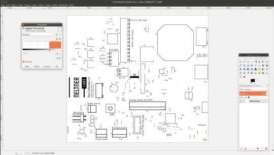
5. You want full contrast, so threshold the image.
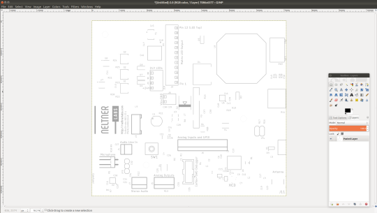
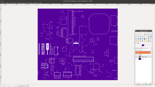
6. Assuming you don’t want a white background for your soldermask, make white your transparent color, add a new layer, and color that layer whatever you want your silkscreen to be. Put the color layer underneath the silkscreen layer. I inverted the colors of the silkscreen since silkscreen is usually white. Using two layers makes this a lot easier.
7. Export the file as a png.
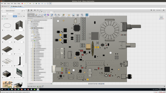
8. In fusion, set your working piece as the PCB. Create a reference plane 0.01mm offset above the PCB body.
9. Create a sketch and project in the edges of your PCB body. Extrude back down *the full width of your PCB (i.e. typically 1.6mm). It will overlap with the PCB body.
10. Now that there is a real body present, it is blocking the view of the PCB canvas. The body is only 10 microns tall, so it shouldn’t cover any 3D parts models.
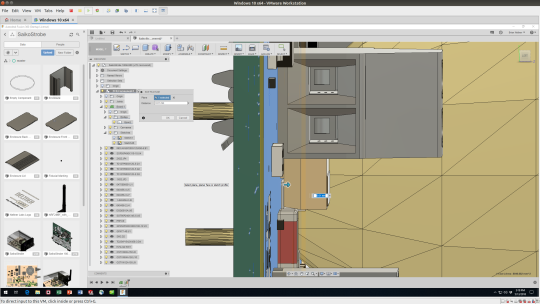
11. Next, go to the appearance menu. Copy up something like white glossy paint, duplicate it, and then edit the duplicated appearance.
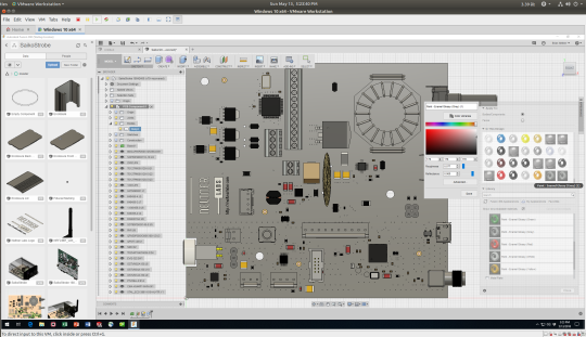
12. There is a secret advanced menu that will let us now do exactly what we want. Right click to edit the material and click on the Advanced Options. There is a drop-down to the right of the Color Selector box and if you click on it you will see that an option is “image”. Click on this and select the image we saved.
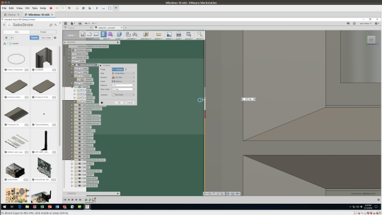
13. The image scaling will make no sense at first. Click on “edit image” which will now appear in the same drop down menu. Make the “Sample Size” in Scale unlinked and set the dimensions to your exact true board dimensions. This will scale the image appropriately. Next, at least on mine, I had to offset it by negative half that distance along each axis to get it placed properly. I unchecked the repeating options.
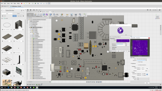
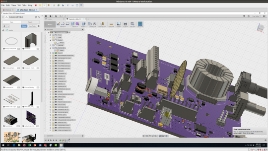
14. Apply the new appearance *TO THE FACE* of the new body. This is what it now looks like in the pre-rendering window.
14. Now, this may well be good enough for you, it’s already a vast improvement. But if you want a real rendering I found that the image tears terribly and shows the green PCB underneath whether I make the two bodies touch or leave a small gap. So instead, just hide the entire PCB body since your custom placed body is the correct thickness already.
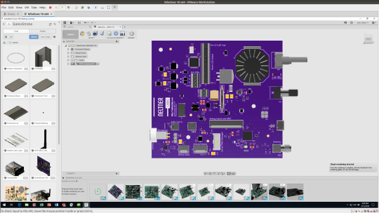
15. Finally, start your rendering. With the PCB hidden your custom outline and image will take priority and override the boring green plank imported from Eagle.
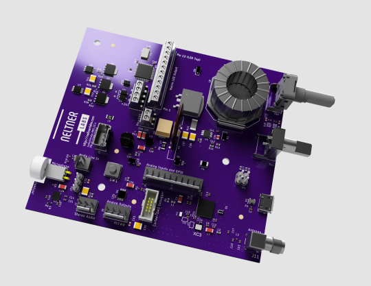
Unfortunately a lot of manual steps, so obviously only do this on something you’re really done with modifying! Hope you enjoyed my tutorial! And I hope the EagleCAD and Fusion 360 teams integrate something similar into their products!
And finally, a video showing the entire assembly with the enclosure!
I will also note that it is possible to do this with a decal. I found the workflow to do this intractable due to the broken scaling of decal images in Fusion 360. The key trick is that “canvases” show in the model but don’t render, while “decals” do. In any case, applying an image to the board appearance works better anyway.